Introduction defining the spring requirements
Although wave spring applications are extremely diverse, there is a consistently basic pattern for defining spring requirements. Those requirements are used to select a stock/standard spring or design a special spring to meet the specifications.
WORKING CAVITY
The working cavity usually consists of a bore the spring operates in and/or a shaft the spring clears. The spring stays positioned by piloting in the bore or on the shaft.
The distance between the Ioading surfaces defines the axial working cavity or work height of the spring.


LOAD REQUIREMENT
The load requirement is defined by the amount of axial force the spring must produce when installed at the work height. Some applications require multiple working heights, where loads at 2 or more operating heights are critical and must be considered in the design. Often minimum and/or maximum loads are satisfactory solutions, particularly where tolerance stack-ups are inherent in the application.

OPERATING ENVIRONMENT
Dynamic Ioading (fatigue), high temperature, a corrosive media or other unusual operating conditions must be considered in spring applications. Solutions to various environmental conditions typically require selection of the optimal raw material and operating stress.
Standard springs vs Special springs
Finding the right spring can be as easy as selecting a standard catalog item. A Smalley engineer can help you choose from over 2000 standard parts available from stock in Carbon and Stainless Steel.
Smalley's "no-tooling'' method of manufacturing provides the utmost in flexibility and quality. Whether the requirement is for 1 spring or 1,000,000 consider Smalley for your special spring requirments
Let Smalley design your spring
Over 50% of Smalley's business is in the design and manufacture of special springs to suit individual applications. Whether it's a technical question, or the most complex spring design, Smalley engineers are always available and welcome the opportunity to assist you.
NOMENCLATURE
b - Radial Width of Material, (in.) [(O.D.- I.D.)÷2]
Dm - Mean Diameter, (in.) [(O.D.+i.D.)÷2]
E - Modulus of Elasticity, (psi)
f - Deflection, (in.)
H - Free Height, (in.)
I.D. - Inside Diameter, (in.)
K - Multiple Wave Factor, see Table 1
L - Length, Overall Linear, (in.)
N - Number of Waves (per turn)
O.D. - Outside Diameter, (in)
P - Load, (Ibs.)
S - Bending Stress, (psi.)
t - Thickness of Material, (in.)
H1 - Work Height, (in.) (H-f)
Z - Number of turns
Table 1

SINGLE TURN GAP OR OVERLAP TYPE
Applications
1. Low-Medium force
2. Low-Medium Spring Rate
3. Short Deflection
4. Precise load/deflection Characteristics
Single Turn Wave Springs provide the most flexibility to designers. There are few restrictions in their design. They are specified in the majority of small axial and radial space constraint applications.
Single Turn Wave Springs are the basic and most common wave spring product. They are used in the widest variety of spring applications due to their lower cost and simplified design configuration.

Formulas

CREST-TO-CREST
Applications
1. Low-Medium force
2. Low-Medium Spring Rate
3. Long Deflection
4. Precise load/deflection Characteristics
Crest-to-Crest Spirawave flat wire compression springs are pre-stacked in series, decreasing the spring rate by a factor related to the number of turns.
Note:
N must be in 1/2 wave increments
Z = numbers of active turns

Formulas

NESTED SPIRAWAVE® (PARALLEL STACKED)
· Higher force
· Higher Spring Rate
· Short Deflection
· Precise load/deflection Characteristics
Nested Spirawave® Wave Springs are pre-stacked in parallel, increasing the spring rate by a factor related to the number of turns.

Formulas

DIAMETER EXPANSION

The formula shown below is used to predict the maximum fully compressed diameter.
Formula

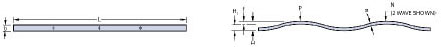
LINEAR EXPANDER
Linear Expander are a continuous wave formed (marcelled) wire length produced from spring temper materials. They act as a load bearing device having approximately the same load/deflection characteristics as a wave spring. Forces act axially or radially depending on the installed position. Axial pressure is obtained by lying the expander flat in a straight line. Circular wrapping the expander (around a piston for example) produces a radial force or outward pressure.
Formulas
STRESS
Operating Stress
Compressing a wave spring creates bending stresses similar to a simple beam in bending. These compressive and tensile stresses limit the amount a spring can be compressed before it yelds or "takes a set". Although spring set is sometimes not acceptable, load and deflection requirements will often drive the design to accept some set or "relaxation" over time.
Maximum design Stress
Static Applications Smalley utilizes the Minimum Tensile Strength found in the "Materials" section to approximate yield strength due to the minimal elongation of the hardened flat wire used in Smalley products. When designing springs for static applications we recommend the calculated operating stress be no greater than 100% of the minimum tensile strength. However, depending on certain applicatrions, operating stress can exceed the minimum tensile strength with allowances for yield strength. Typical factors to consider are permanent set, relaxation, loss of load and/or loss of free height.
Dynamic Applications When designing wave springs for dynamic applications, Smalley recommends that the calculation of operating stress not exceed 80% of the minimum tensile strength. Refer to the "fatigue Stress ratio" and Table 2 for further fatigue guidelines.
Residual Stress/Pre-Setting
Increasing the load capacity and/or fatigue life can be achieved by compressing a spring beyond its yield point or "presetting". Preset springs are manufactured to a higher than needed free height and load and then compressed solid. Both the free heigher and load are reduced and the material surfaces now exhibit residual stresses, which enhance spring performance.
FATIGUE
Fatigue cycling is an important consideration in wave spring design.
The fatigue guidelines in Table 2 provide a slightly more conservative approach and allow for calculation of cycle life between 2 work heights. Although these methods of fatigue analysis have proven to be a good approximation, testing is recommended whenever cycle life is critical.
Formula:

X = Fatigue stress ratio, refer to Table 2
s = Material tensile strength
S1 = Calculated stress at lower work height (must be less than s)
S2 =Calculated stress at upper work height
Table 2

LOAD/DEFLECTION
A comparison of the actual spring rate to the theoretical (calculated) spring rate provides practical limits for the working range of the spring.
Figure 1 shows a graph of theoretical and tested spring rate. Typically, theoretical rate is accurate until the spring starts to bottom out or reach it's "solid height".
As a general rule, the calculated spring rate is accurate through the first 80% of available deflection and for work heights down to 2 times the solid height. Although the spring can operate beyond this "linear" range, measured loads will be much higher than calculated.
Figure 1

HYSTERESIS
Wave springs exert a greater force upon loading and lower force upon unloading. This effect is know as hysteresis. A graphic representation is shown by the shaded area between the curves in Figure 2.
In a single turn spring, friction due to circumferential and radial movement are the prime causes. Spirawaves also contribute to the frictional loss as adiacent layers rub against each other. Sufficient lubrication will minimize this effect.
Figure 2

DESIGN GUIDELINES
Material cross-section
Material cross-section plays an important role in Wave Spring design. The most economical materials are those used in manufacturing Smalley standard springs and retaining rings. In addition, many other material cross sections are commonly used in special spring manufacture and are readily available. Smalley engineering can provide assistance in selecting an economical alloy and cross section.
As a basic guideline, use our standard 'SSR'-Wave Spring series for cross-section/diameter relationships. Lighter material sections are usually acceptable. Heavier sections for a given diameter may be incorporated using the following information:
Special Wave Spring design criteria for selecting material cross-sections:
Maximum material thickness = standard ("SSR...") Thickness · 2
Maximum radial wall = material thickness (any value) · 10
Minimum radial wall = material thickness (any value) · 3
For Overlap Type Wave Springs and multiple turn Spirawaves, the Radial Wall must be sufficient to prevent misalignment between adjacent layers. For springs with a narrow Radial Wall, radial misalignment can occur during handling or during operation if the spring is not contained or closely piloted.
Solutions to this problem include dimensioning the spring to pilot closely on the I.D. and/or O.D. or designing the spring as a single turn Gap Type.
Diameters
Figure 3 illustrates the preferred method of specifying diameters. In either case, the spring diameter is developed to provide proper operation between the bore and the shaft.
NOTE: Smalley's manufacturing process of edgewinding controls either the O.D. or the l.D. The material radial wall is also tightly controlled. Therefore whenever possible, tolerance only one diameter and the radial wall instead of tolerancing both the O.D. and l.D.
Bore Pilot
For springs that pilot in the bore as shown in figure 3a, the bore and shah diameters should be included in the spring specifications. Commonly used requirements would read:
"Spring must pilot and operate in a (minimum bore) bore diameter."
Spring must clear a (maximum shaft) shaft diameter."
The actual spring diameter is then developed at time of manufacture to provide the best fit and prevent binding due to expansion.
For gap type and overlap type springs, the outside diameter can be specified because binding is not a concern. The outside diameter can be toleranced to provide a minimum clearance in the bore or provide cling in the bore, as do the Smalley Bearing Prelude springs
Shaft Pilot
For springs that pilot on a shaft as shown in Figure 3b, the inside diameter can be toleranced to provide a minimum clearance from the shaft. Since wave springs expand during compression, interference with the shaft is generally not a concern.
To insure proper operation, include shaft and bore diameters in the spring specifications.
Commonly used requirements would read:
"Spring pilots over and clears a (maximum shaft) shaft diameter."
"Spring operates in a (minimum bore) bore diameter."


Ball bearing disc springs, Slotted and plain")