Through parallel and series arrangements of individual disc springs, it is possible to realise higher spring loads and larger spring deflections.

Figure 7
Disc Springs Arranged in a Single Series Stack.
For i disc springs arranged in single series, the following values will apply:
ng values will apply:
Ftot = F
Stot = i · s
Lo = i · Io

Figure 8
Disc Spring Component Consisting of Two Disc Springs Arranged in Parallel (n=2).
For n disc springs arranged in a parallel stack, the following values will apply:
Ftot = n · F
Stot = s
Lo = Io + (n' 1) · t
For disc springs with looad-bearing surfaces and a reduced material thickness, t must be replaced with the value t'.

Figure 9
Disc Spring Components Consisting of Two Disc Springs in Parallel (n-2) Arranged in a Series Stack Combination (i=4).
For i disc spring components in series, each component consisting of n disc springs in parallel, the following values will apply:
Ftot = n · F
Stot = i · s
Lo = i · [Io + (n' 1) · t]
For disc springs with load-bearing surfaces and a reduced material thickness, t must be replaced with the value t'
In the above Figures and the following load/deflection characteristic curves (Figures 10- 13), the frictional influences affecting the disc springs have not been taken into consideration (see Chapter 9). For i > 1 and with markedly regressive characteristic curves the total travel stot becomes increasingly uneven in the individual disc springs or disc spring components. The reason for this is the difference in load from disc spring to disc spring and the effects of friction in the disc spring stack.
Therefore, disc springs with ho/t > 1.3 or K4 · (h'o/t') > 1.3 should not be used in disc spring stacks.
Schematic Diagrams of Load/Deflection Characteristic Curves for Disc Springs in Parallel and Series Combinations
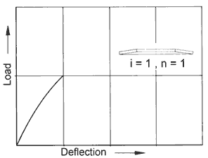
Figure 10:
Load/Deflection Characteristic Curve of the Single Disc Spring.
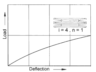
Figure 11:
Load/Deflection Characteristic Curve of a Disc Spring Stack
Consisting of Four Disc Springs Arranged in Single Series (i=4 and n=1).
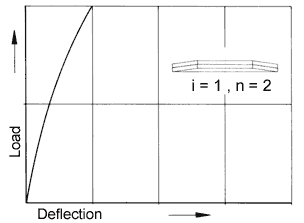
Figure 12:
Load/Deflection Characteristic Curve of a Disc Spring Stack
Comprised of a Disc Spring Component of Two Disc Springs in Parallel (i=1 and n=2).
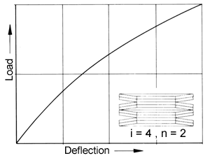
Figure 13:
Load/Deflection Characteristic Curve of a Disc Spring Stack Consisting of Four Disc Spring Components in Series, Each Component Consisting of Two Disc Springs in Parallel (i=4 and n=2).
Progressive Load/Deflection Characteristic Curves
For disc springs which are used in disc spring stacks and which have a linear or regressive load characteristic curve, special measures must be taken to provide a progressively increasing load. All of the possible solutions here described follow the same principle.
A disc spring stack may be "split" into a number of component stacks. These components are then connected in series through the flow of the load. By providing an appropriate stroke for a component so that it is compressed flat at a predetermined force, the remaining component or components can continue at the required higher spring rate.
Disc Spring Stack Consisting of Disc Springs of Different Thicknesses
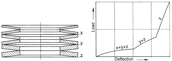
Figure 14:
Progressive Load/Deflection Characteristic Curve Obtained By Means of a Combination of Disc Springs of Different Thicknesses.
The disc springs in part x of the stack are flattened when they reach load Fx and contribute no further spring action. In part y of the stack the disc springs act in the same way when load Fy is reached.
Spring Stacks Consisting of Parallel Components of Different Numbers of Disc Springs Arranged in Series
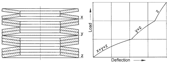
Figure 15:
Progressive Load/Deflection Characteristic Curve Obtained by Means of Disc Spring Components Consisting of a Varying Number of Disc Springs in Parallel Per Component.
A variation in the load carrying capability of each component part of the disc spring stack is achieved by varying the number of disc springs in parallel.
Disc Spring Stacks with Deflection Limiting Rings of Different Thicknesses
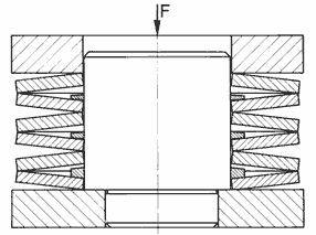
Figure 16:
Progressive Load/Deflection Characteristic Curve Obtained by Means of Load Limiting Rings of Varying Thicknesses.
Through the use of deflection limiting rings of different thicknesses, component parts of the stack are progressively prevented from further travel as the force increases.
In general, it must be realised that the life expectancy of the entire disc spring stack assembly will be determined by the stress conditions of the most highly stressed component part in the assembly.
Installation Recommendations for cb
In the dynamic cycling of disc springs in stacks, there is a small relative movement in a radial direction between the end disc springs and the end plates. This leads to wear as a consequence of the high line contact pressure. The contact pressure is lower when the larger, outside diameter of the disc spring and not the inside diameter, is against the end plate.
When an uneven number of disc springs must be used in a disc spring stack, the disc spring at the end of the stack on the moving end of the stack (relative to the movement between the end disc spring and the guide element) should be oriented in such a manner that the outside diameter surface of the disc spring is in contact with the end plate.
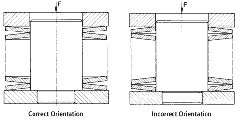
Figure 17:
Orientation of the End Spring in a Disc Spring Stack Consisting of an Even Number of Disc Springs.
When an uneven number of disc springs must be used in a disc spring stack, the disc spring at the end of the stack on the moving end of the stack (relative to the movement between the end disc spring and the guide element) should be oriented in such a manner that the outside diameter surface of the disc spring is in contact with the end plate.
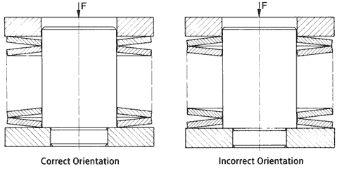
Figure 18:
Orientation of the End Disc Spring in a Disc Spring Stack Consisting of an Uneven Number of Disc Springs.
Lubrication
Satisfactory lubrication has a critical influence on the guide characteristics, the friction and the wear and consequently on the fatique life. Depending upon the application involved, oil baths, greases, pastes containing molybdenum disulphide, friction reducing laquers and other forms of lubricants will be found to be useful.
Recommended Clearances Between Guide Elements and Disc Springs (DIN 2093)
Adequate "clearance" is required between the disc springs and their guide elements. Internal guiding on the inside diameter by means of guide rods is the preferred guiding method. For outside diameter guiding, a guide sleeve may be used.
Clearance Between Guide Elements and the Guided Disc Spring Diameter (difference between the Diameters):
table 5

Technical Requirements for Guide
Dynamic Loading
It has been proven over time that hardened and polished guide elements and thrust plates provide the best performance for dynamic loading of disc springs. The hardened surfaces of these particular parts should be at least 55 H RC, and the minimum depth of hardness should be 0.80 mm. If nitriding is found to be required, particular attention must be paid to the stresses of the base material to ensure that the relatively thin nitriding layer is not compromised during use.
Static Loading
For truly static applications, either heat treated or nonheat treated guide elements and end plates may be used.


