Self-Centering Disc Springs
Difficulties which occur as a result of the friction between the guide element and the disc spring have raised the question whether it is possible to work without conventional guidance elements. A number of solutions to this problem have been developed where friction can either be neglected or at least be relatively low and reproducible.
Guiding by Cylindrical "Shoulders" at the Inside and Outside Diameters
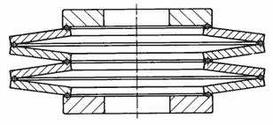
Figure 27:
Disc Spring Stack Guided by Cyíindrical "Shouiders"
This method is especially usefull for disc springs which are to be machined all over.
Guiding by Means of Intermediate Rings
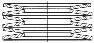
Figure 28:
Disc Spring Stack Guided By Intermediate Rings
Disc Springs can be held in position relative to one another through the use of intermediate rings with a T-shaped cross section.
Guiding by Balls or Wire Rings
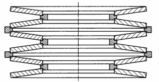
Figure 29:
Disc Spring Stack Guided By Balls or Wire Rings
It is possi ble to man ufactu re disc springs with ci rcu l ar grooves near the outside diameter on the concave side and near the inside diameter on the convex side. The guiding is then accomplished by means of a large number of small ball bearings or a wire ring which completely fill the groove.
Disc Springs as Elements in Switches
Disc springs which have a curve parameter ho/t or K4 · (h'o/t') > √2 exhibit a load/deflection characteristic curve with a negative sloping section; for ho/t or K4 · (h'o/t') > √8, the disc spring load will become somewhat negative. As a result, disc springs of these types are commonly used as switches and control elements.
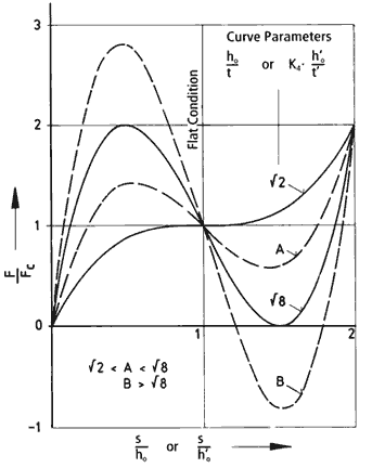
Figure 30:
Calculated Load/Deflection Characteristic Curve as a Function of the Ratio ho/t or K4·(h'o/t').
Switches with Load/Deflection Characteristic Curve - Type A
This is a force controlled element which exhibits a "snap-through" effect between points 1 and 2 as well as at points 3 and 4. Increasing load on the disc spring brings the spring to point 1. From this point, a sudden "snap" action will occur which forces the disc spring to invert beyond the flat position and arrive at point 2. As the load on the spring is reduced, point 3 will be reached, at which time the spring will, once again, "snap" through the flat position to arrive at point 4.
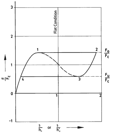
Figure 31:
Calculated Load/Deflection Characteristic Curve - Type A
Switches with Load/Deflettion Characteristic Curve - Type B (Bi-Stable Disc Springs)
The load/deflection characteristic curve for disc springs of this type is such that the load at points x, y and z is zero. The equilibrium of the disc spring at point y is unstable. If the spring is disturbed, it will immediately "snap" through to either of the stable positions (point x or point z). This part can be both force and deflection controlled.
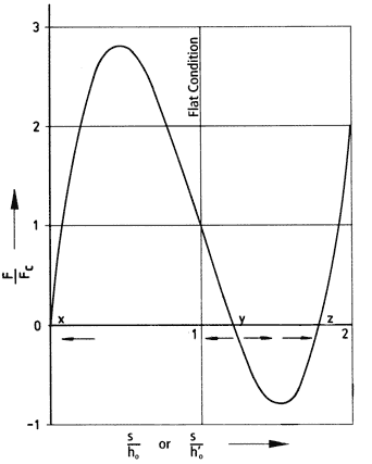
Figure 32
Calculated Load/Deflection Characteristic Curve - Type B
Slotted Disc Springs
As an approximation, slotted or "fingered" disc springs can be thought of as conventional disc
springs (outside annular rim) with stiff "fingers" (lever arms) reaching from the inner edge towards the center. Depending upon the length of these levers, the tip of the "fingers" deflects proportionately more than the inner edge of the "true" disc spring. In reverse ratio the applied load required at the ends of the "fingers" is reduced.
For slotted or "fingered" disc spring calculations, refer to the equations in Chapter 4. The coefficient K4 is then defined by:

The above calculation is a reasonable approximation provided the "fingers" are relatively narrow, so that the flow of the stresses in the outer ring shaped section of the spring is only minimally disturbed. Any bending of the fingers can be neglected.
Disc springs which are slotted on the outside diameter, as well as disc springs which have been slotted on both the inside and outside diameters, are currently being manufactured for use in specialized applications; however, slotting on the inside diameter is preferred for a number of reasons.
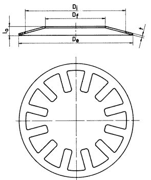
Figure 33:
Example of an internally slotted disc spring.


